VLAN 통신 예제
1. 네트워크 토폴로지 구성
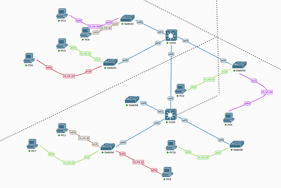
토폴로지 환경 -> L3 switch: 2, L2 switch: 6, PC: 10
2. 각 장비에 VLAN 설정하기
1. Core 설정 - L3 switch
enable
configure terminal

! VLAN 생성
vlan 10
name Tech
exit
vlan 20
name Sale
exit
vlan 30
name Intern
exit
vlan 40
name Accountant
exit
vlan 99
name Management
exit

! VLAN 인터페이스에 IP 할당
interface vlan 10
ip address 192.168.10.1 255.255.255.0  ! Core1의 경우
! ip address 192.168.10.2 255.255.255.0  ! Core2의 경우
no shutdown
exit

interface vlan 20
ip address 192.168.20.1 255.255.255.0  ! Core1의 경우
! ip address 192.168.20.2 255.255.255.0  ! Core2의 경우
no shutdown
exit

interface vlan 30
ip address 192.168.30.1 255.255.255.0  ! Core1의 경우
! ip address 192.168.30.2 255.255.255.0  ! Core2의 경우
no shutdown
exit

interface vlan 40
ip address 192.168.40.1 255.255.255.0  ! Core1의 경우
! ip address 192.168.40.2 255.255.255.0  ! Core2의 경우
no shutdown
exit


interface Ethernet0/0
switchport trunk encapsulation dot1q -> 트렁크 포트가 802.1Q 프로토콜을 사용하여 VLAN 태그를 붙이도록 설정
switchport mode trunk -> 포트 trunk 모드로 설정
switchport trunk allowed vlan 10,20,30,40,99 -> 허용된 VLAN 설정
no shutdown
exit

interface Ethernet0/1
switchport trunk encapsulation dot1q
switchport mode trunk
switchport trunk allowed vlan 10,20,30,40,99
no shutdown
exit

interface Ethernet0/2
switchport trunk encapsulation dot1q
switchport mode trunk
switchport trunk allowed vlan 10,20,30,40,99
no shutdown
exit

interface Ethernet0/3
switchport trunk encapsulation dot1q
switchport mode trunk
switchport trunk allowed vlan 10,20,30,40,99
no shutdown
exit

! Inter-VLAN 라우팅 활성화
ip routing

end
write memory
2. Access switch 설정
enable
configure terminal

! VLAN 생성
vlan 10
name Tech
exit
vlan 20
name Sale
exit
vlan 30
name Intern
exit
vlan 40
name Accountant
exit
vlan 99
name Management
exit

! 관리 IP 설정
interface vlan 99
ip address 172.16.1.11X 255.255.255.0  ! X는 스위치 번호
no shutdown
exit

! 기본 게이트웨이 설정
ip default-gateway 172.16.1.1

! 트렁크 포트 설정 (코어 스위치로 연결)
interface e0/0  ! 실제 인터페이스 이름 확인 필요
switchport trunk encapsulation dot1q
switchport mode trunk
switchport trunk allowed vlan 10,20,30,40,99
no shutdown
exit

! 액세스 포트 설정 (PC 연결)
interface Ethernet0/1  ! 토폴로지에 맞게 인터페이스 번호 조정
switchport mode access
switchport access vlan XX  ! XX는 PC가 속한 VLAN 번호(10, 20, 30, 40)
no shutdown
exit

end
write memory
3. 각 장비에 맞는 IP 설정
PC1> ip 192.168.40.101 255.255.255.0 192.168.40.1
PC2> ip 192.168.20.102 255.255.255.0 192.168.20.1
PC3> ip 192.168.20.103 255.255.255.0 192.168.20.1
PC4> ip 192.168.30.104 255.255.255.0 192.168.30.1
PC5> ip 192.168.30.105 255.255.255.0 192.168.30.1
PC6> ip 192.168.10.106 255.255.255.0 192.168.10.1
PC7> ip 192.168.20.107 255.255.255.0 192.168.20.1
PC8> ip 192.168.10.108 255.255.255.0 192.168.10.1
PC9> ip 192.168.40.109 255.255.255.0 192.168.40.1
PC10> ip 192.168.20.110 255.255.255.0 192.168.20.1
4. 통신 확인
1. 같은 VLAN 대역 통신
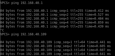
2. 다른 VLAN 대역 통신
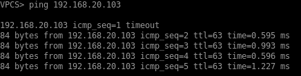
Core가 L3 Switch 또는 Router인 경우에만 그 외 대역도 통신이 가능함
L2 Switch일 경우에는 같은 VLAN 대역 통신만 가능